...
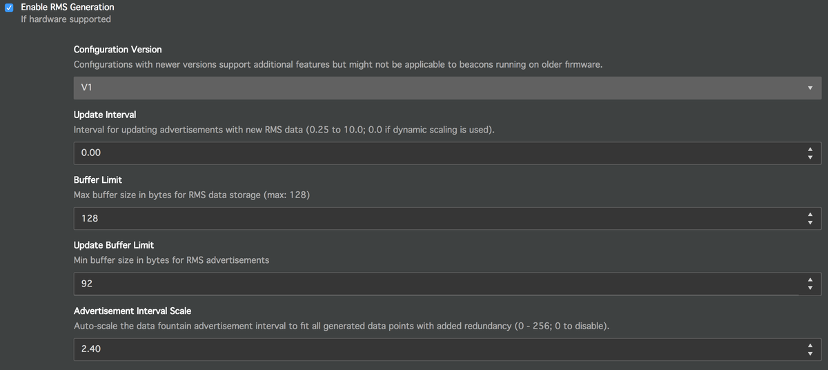
Since manually calculating the required output rate of a beacon can be rather sophisticated the beacon allows you to specify an Advertisement Interval Scale parameter instead. If this parameter is set, the beacon's firmware will take care of automatically scaling the beacon's Data Fountain broadcast rate to a value that allows the beacon to broadcast all of the beacon's collected output data. The manually selected Data Fountain broadcast rate will then be overwritten by the beacon internally. The value of the Advertisement Interval Scale represents the redundancy factor of generated advertisements. The value in the screenshot below (2.40) would ensure that the beacon produces the required amount of packets multiplied by a factor of 2.4.
Filter Configuration
Raw acceleration data that is collected in order to generate feature values on the beacon can be filtered - e.g. in order to extract the desired frequency components. Bluzone's default templates for Condition Monitoring come with a default filter configuration that should work in most use cases. All of the available filters can however be fully adapted in order to use custom settings.
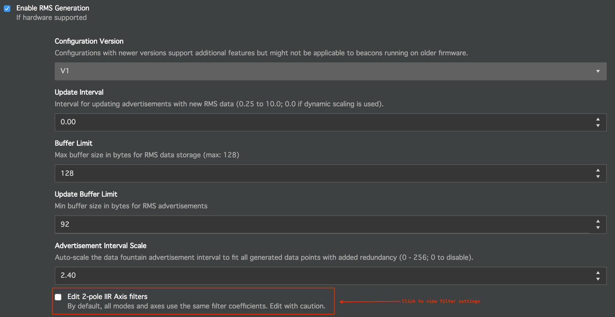
The filter configuration is by default not visible in the Bluzone Console. These are expert settings that can be adjusted after clicking the appropriate checkbox in a Beacon's or Tempate's configuration settings.
There are 2 individual filters for each acceleration axis of a beacon. As a result there is a total of 6 filters that can be configured on each beacon:
- X Axis Filter 1
- Y Axis Filter 1
- Z Axis Filter 1
- X Axis Filter 2
- Y Axis Filter 2
- Z Axis Filter 2
Filters 1 and 2 for each axis have a different purpose depending on which configuration version you are working with:
- V1 Configurations
Uses filter 1 in low speed mode and filter 2 in high speed mode. For details about beacon modes, please see the appropriate section below.
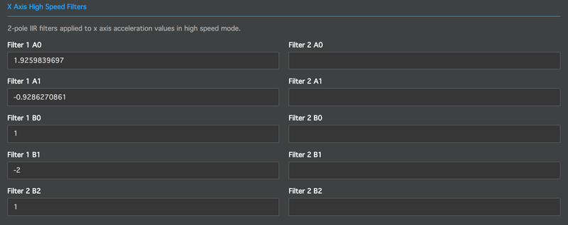
The screenshots below show the low speed and high speed filter configurations for a beacon's X acceleration axis as it will be visible for V1 configurations.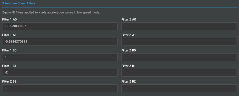
- V2 Configurations
The output of filter 1 is used to calculate acceleration based features in both low and high speed mode.
The output of filter 2 is used to convert raw acceleration into velocity in both low and high speed mode.
The below screenshots show the acceleration and velocity filter configurations for a beacon's X acceleration axis as it will be visible for V2 configurations.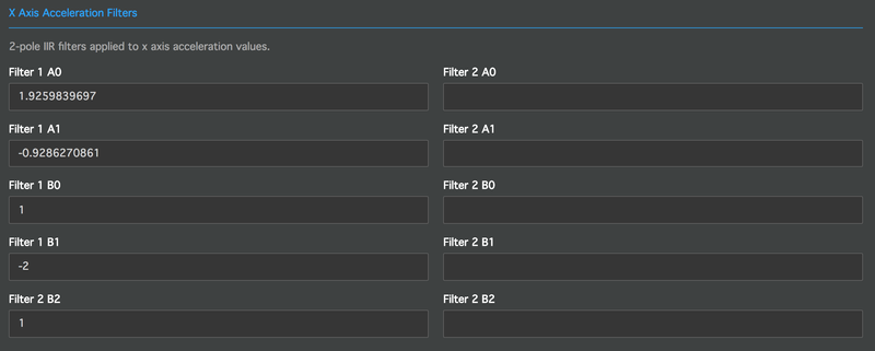
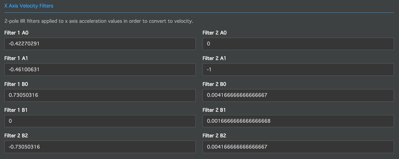
Each of the 6 available filters consists of 2 normalized Digital Biquad Filter sections. Raw acceleration data will flow into the first of these sections and get filtered based on its coefficients. The output of the first filter section will then flow into the second filter section. The output of the second filter section will then be collected and aggregated into the desired output features of the beacon. Therefore the coefficients that can be configured for each of the 6 beacon filters are the following (as seen in screenshots above):
- Filter 1 B0
- Filter 1 B1
- Filter 1 B2
- Filter 1 A0
- Filter 1 A1
- Filter 2 B0
- Filter 2 B1
- Filter 2 B2
- Filter 2 A0
- Filter 2 A1
Note:
We do not recommend that end users manually alter filter settings unless they are familiar with the underlying principles and/or have professional experience in this field. Altering filter settings can lead to unwanted results in a beacon's output values.
Low Speed and High Speed Configuration
...